We received an email with the following question:
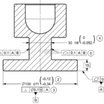
I’ve attached a simplified illustration for a drawing I encountered at work, I would be grateful if you could please help me understand the intention and if it is acceptable standard practice.
Is it possible to specify a profile tolerance of 0.1 related to a Datum System (ISO) / Reference Frame (ASME) to both surfaces of a tab.
And apply simultaneously a narrower size tolerance of 0.052?
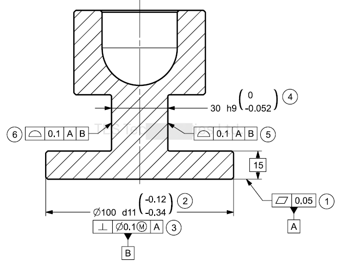
Figure 1
Answer:
Possible: Yes (just like you can kerosine, if you really want to)
Advisable: Absolutely, absolutely not!
If the intention is
To have a tight size tolerance and release location and orientation to set minimum geometric specifications to meet the following functional specifications:
- The tab should have a slide fit with an open 30 millimeter spanner wrench
- location and orientation are relative to datum axis B perpendicular to datum plane A which the base surface is tangent to.
Then
- Size Variation limits should be 30h9 (-0.052\0)mm ,and perfect form at MMC should not be violated (the feature must fit between two parallel planes with an offset of 30)
- Location and orientation may vary by 0.1 mm -> Position to the |A|B| system, which locates (and also controls orientation) of the centerline of the 30 tab relative to the reference system
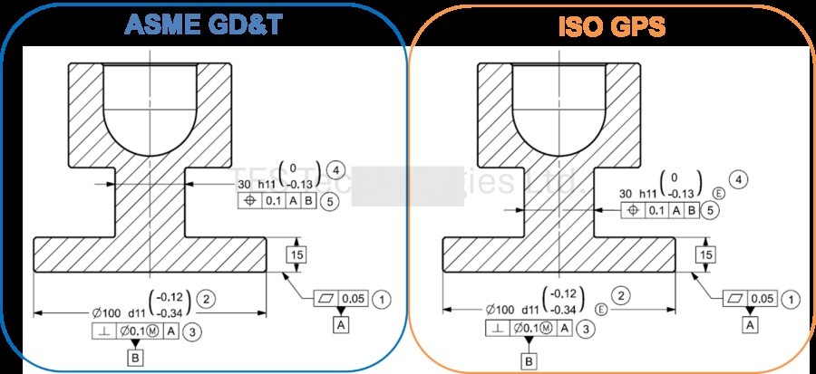
Figure 2
Explanation:
A drawing should document design intent
A dimension with a linear tolerance should be used when a fit condition is required between mating features of two different workpieces.
Position controls location and orientation of a centerline, axis, or point. And completes the size specification with no overlap (Opening the option to add material modifiers when needed to relax specification limits)
Combining size with a linear tolerance and a profile obscures design intent, since it holds an inherent overlap between size and profile
The tolerance on size 30 specifies the distance between pairs of opposite points is between 14.948-15.000
The Profile controls each of the tab surfaces individually allowing the distance between opposite points to be between 14.9-15.1. In contrast to Position, which only controls form and orientation, Profile introduces ambiguity because Profile also controls location Orientation form and in this case also size.
So to keep design intent clear,
Use the proper tool (not the possible tool)