How many times have you come across drawings with odd dimensions?
How many times have you encountered multiple revision marks on a single dimension?
The root cause for most dimensional Revisions are:
- Manufacturing request to relax a tolerance
- Assembly Fit or Function issues (Failure), hopefully before shipping to the client
Figures 1 and 2 depict an example (based on a real case) of a dimension that underwent several changes due to a manufacturing change request (tolerance change), and assembly functional issues (unsmooth movement, sliding disturbances – dimension change).
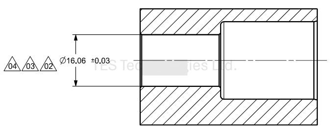
In Figure-1 there are three Revision Marks on a single size specification. At first glance, the nominal size appears odd (why not 16 or 16.1?). In search of logic, examining the Shaft drawing (Figure 2) that mates with the Hole (Figure 1).
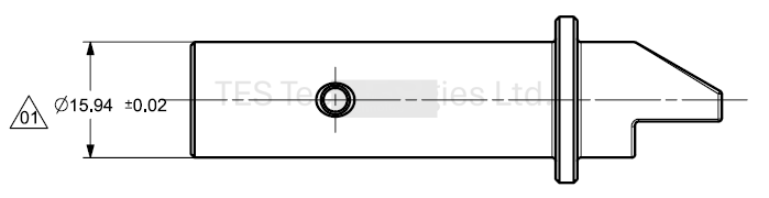
Once again, the nominal size is odd, and there is a Revision Mark associated with the Size (checking Revision History on both drawings shows that the shaft size was modified at the same date as change 2 in the Shaft).
Four Revisions due to a single interface between two parts indicate repeated failures (Tight tolerance – Manufacturing issue, or Assembly Fit or Function issues)
Was it possible to mitigate all these failures upfront?
The answer is positive
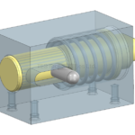
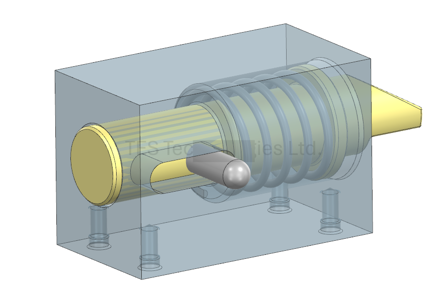
Looking at the assembly (Figure-3) and product specifications, the product is a spring-loaded latch, exposed to corrosive effects (salty water) and contamination (dust and mud).
Latch shall be manipulated manually and slide freely under any condition.
A quick internet search for “Slide Fit Tolerance” or (Heaven forbid, picking an Engineering Handbook from the shelf) yielded the following recommendation:
Clearance fits:
H11/a11, H11/c11, H11/c9, H11/d11, A11/h11, C11/h11, D11/h11
– Fits with great clearances with parts having great tolerances.
– Use: Pivots, latches, fits of parts exposed to corrosive effects, contamination with dust, and thermal or mechanical deformations.
Recommended tolerances are per ISO 286 standard (Tolerance values may also be found online, including calculators and fit recommendations). The ISO code system for tolerances is supported by all CAD software (no need to seek the tolerance limit values).
Note: When applying the ISO code system for tolerances, the envelope requirement also known as “Taylor’s Principle” (Perfect Form at MMC), is necessary for application. Perfect Form at MMC is the default in the American standard ASME; using ISO GPS it must be explicitly indicated by the symbol Ⓔ.
ISO Fit System consists of three symbols:
The tolerance class contains information on the tolerance magnitude and the placement of the tolerance interval relative to the nominal size of the feature.
1. Nominal Size: of a feature of perfect form as defined by the drawing specification
2. Fundamental Deviation: limit deviation that defines the placement of the tolerance interval in relation to the nominal size. The fundamental deviation is identified by a letter
3. IT (International Tolerance Grade): Tolerance magnitude – again depending on the nominal size. The IT Grade is identified by a number.
Note: IT Grades are related to manufacturing technology and cost.
So in back to our case:
– Changing the nominal size from odd values (16.06 and 15.94) to 16, shared by both features
– Handbook recommended Fit is H11\c11 (for nominal 16, the extremes for the interval are 0.095-0.315)
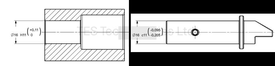
Note that recommended tolerances to achieve required functionality in the given conditions are wider than the last revision of both parts, needless precision is relaxed.
– The hole tolerance is relaxed almost twice (from 60 microns to 110 microns)
– The shaft tolerance is relaxed almost three times (from 40 microns to 110 microns)
What about the risks:
A manufacturer fails to meet the required tolerance
IT Grade can be mapped to manufacturing technology
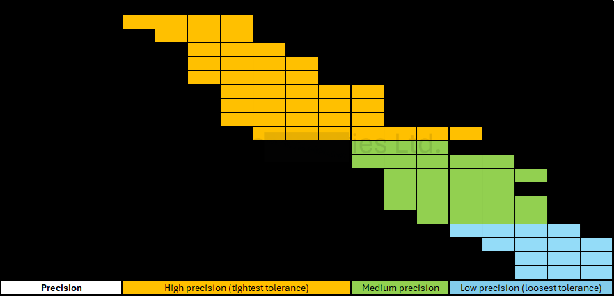
The recommended IT Grade, IT 11, is medium. Using the IT Grade gives the designer a perspective of the given tolerance (manufacturability and relative cost).
The risk of an Engineering Change Request by manufacturing will decrease significantly!
Assembly Fit or Function risk (Failure)
– Relying on technical literature for generic problems saves time (saves the effort of reinventing the wheel, trying to determine fit tolerances to achieve function)
– Assembly Fit or Function risks are significantly reduced when we rely on an engineering handbook (based on over 100 years of real world industrial experience).
Additional benefits:
– Preserve design intent. Share Nominal size value on both features, and apply appropriate Tolerance Grades to establish Fit.
– If a change is still required, then the change is easier to perform (tolerance change only, no model update required).
– Checking drawings and dimensional management becomes easier and faster (Shaft\Hole or Slot\Tab have the same nominal value).
– For standard tolerance grades, there are standard manufacturing tools (encoders…) and inspection gauges (pins, blocks, ring gauges…), so do not be afraid to apply a standard tolerance that is unilateral!
In conclusion
For all cases that require a FIt relation between two features in the assembly:
Clearance, Transition, or Interference
It is highly recommended to apply a Standard Tolerance Class to reduce production and inspection risks (performance, time, and cost) and risks of fit and function.
Note: In this example, there is no effect of additional Geometric variation (Location or Orientation) beyond the size (and Perfect Form in MMC). It is important to note that Location and Orientation constraints must be accounted for when designing parts with fit requirements.
שאלות? תגובות? כיתבו לנו – info@TES-tec.net.