

Size and Envelope
Tip based on a question regarding unclear specification on a tube ISO GPS drawing. (Figures are intended only as illustrations to aid understanding) Questions: An
Size Risk Mitigation; Practical Study Case
How many times have you come across drawings with odd dimensions? How many times have you encountered multiple revision marks on a single dimension? The

Specification applicable range
Between symbolic A question that came up in our GD&T WhatsApp group. When the between symbol is used, as in figure 1, on the profile
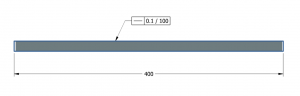
Straightness per unit length
Straightness and flatness per unit length are required when it is necessary to avoid sharp changes over a feature’s length or surface unit. Figure 1
Symmetry & Center Lines are not the same
There is some confusion in the industry regarding Symmetry and Center Lines. I this Tip we will attempt to set things straight, as to ASME

Symmetry & Concentricity
ASME GD&T Symmetry and Concentricity symbols are no longer supported by ASME Y14.5-2018, “Both have been eliminated because other characteristics provide more direct control of

TYPICAL – Once and for All
A drawing is a binding contractual document. The drawing and all terms and symbols used must be unambiguous! In order to reduce the risk of

Wall thickness – Tolerance Stack
(This tip is compliant with ASME; for ISO it is necessary to add E to the dimensions of the wave diameter in Figure 1, a

Welded Assembly
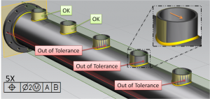
Are geometric tolerances only applicable for machining? (ASME Y14.5-2009, ISO 1101:2012) This tip’s frame story is a fable, but the lessons learned are real. The
Welded Assembly part 2
Reading a drawing – what are the permitted deviation limits? (ASME Y14.5-2009, ISO 1101:2012) This post is the second in a series dealing with a